- 您现在的位置:买卖IC网 > Sheet目录3769 > ATMEGA8515-16JUR (Atmel)MCU AVR 8KB FLASH 16MHZ 44PLCC
115
ATmega8515(L)
2512K–AVR–01/10
Phase and Frequency Correct
PWM Mode
The phase and frequency correct Pulse Width Modulation, or phase and frequency cor-
rect PWM mode (WGM13:0 = 8 or 9) provides a high resolution phase and frequency
correct PWM waveform generation option. The phase and frequency correct PWM
mode is, like the phase correct PWM mode, based on a dual-slope operation. The coun-
ter counts repeatedly from BOTTOM (0x0000) to TOP and then from TOP to BOTTOM.
In non-inverting Compare Output mode, the Output Compare (OC1x) is cleared on the
Compare Match between TCNT1 and OCR1x while upcounting, and set on the Com-
pare Match while downcounting. In inverting Compare Output mode, the operation is
inverted. The dual-slope operation gives a lower maximum operation frequency com-
pared to the single-slope operation. However, due to the symmetric feature of the dual-
slope PWM modes, these modes are preferred for motor control applications.
The main difference between the phase correct, and the phase and frequency correct
PWM mode is the time the OCR1x Register is updated by the OCR1x Buffer Register,
(see Figure 54 and Figure 55).
The PWM resolution for the phase and frequency correct PWM mode can be defined by
either ICR1 or OCR1A. The minimum resolution allowed is 2-bit (ICR1 or OCR1A set to
0x0003), and the maximum resolution is 16-bit (ICR1 or OCR1A set to MAX). The PWM
resolution in bits can be calculated using the following equation:
In phase and frequency correct PWM mode the counter is incremented until the counter
value matches either the value in ICR1 (WGM13:0 = 8), or the value in OCR1A
(WGM13:0 = 9). The counter has then reached the TOP and changes the count direc-
tion. The TCNT1 value will be equal to TOP for one timer clock cycle. The timing
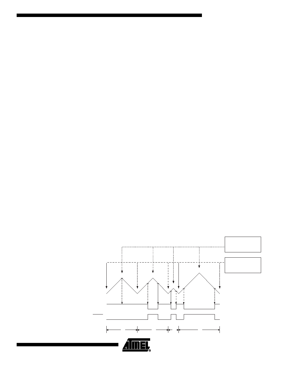
diagram for the phase correct and frequency correct PWM mode is shown on Figure 55.
The figure shows phase and frequency correct PWM mode when OCR1A or ICR1 is
used to define TOP. The TCNT1 value is in the timing diagram shown as a histogram for
illustrating the dual-slope operation. The diagram includes non-inverted and inverted
PWM outputs. The small horizontal line marks on the TCNT1 slopes represent Compare
Matches between OCR1x and TCNT1. The OC1x Interrupt Flag will be set when a Com-
pare Match occurs.
Figure 55. Phase and Frequency Correct PWM Mode, Timing Diagram
R
PFCPWM
TOP
1
+
()
log
2
()
log
-----------------------------------
=
OCRnx/TOP Update and
TOVn Interrupt Flag Set
(Interrupt on Bottom)
OCnA Interrupt Flag Set
or ICFn Interrupt Flag Set
(Interrupt on TOP)
1
2
3
4
TCNTn
Period
OCnx
(COMnx1:0 = 2)
(COMnx1:0 = 3)
发布紧急采购,3分钟左右您将得到回复。
相关PDF资料
PCA9555D/G-T
IC I/O EXPANDER I2C 16B 24SOIC
ATMEGA48-15AZV
MCU AVR 4K FLASH 15MHZ 32-TQFP
ATMEGA48-15AZ
MCU AVR 4K FLASH 15MHZ 32-TQFP
MIC74BQS
IC I/O EXPANDER I2C 8B 16QSOP
EXPANDIO-USB-PT-FS
IC I/O EXPANDER USB 32B 44TQFP
MAX7300ATL+
IC I/O EXPANDER 2WIRE 40TQFN
MAX7300ATL+T
IC I/O EXPANDER 2WIRE 40TQFN
MAX7300AAX+T
IC I/O EXPANDER I2C 28B 36SSOP
相关代理商/技术参数
ATmega8515-16MC
功能描述:8位微控制器 -MCU AVR 8K FLASH 512B EE SPI/UART/TWI 5V RoHS:否 制造商:Silicon Labs 核心:8051 处理器系列:C8051F39x 数据总线宽度:8 bit 最大时钟频率:50 MHz 程序存储器大小:16 KB 数据 RAM 大小:1 KB 片上 ADC:Yes 工作电源电压:1.8 V to 3.6 V 工作温度范围:- 40 C to + 105 C 封装 / 箱体:QFN-20 安装风格:SMD/SMT
ATmega8515-16MI
功能描述:8位微控制器 -MCU AVR 8K FLASH 512B EE SPI/UART/TWI 5V RoHS:否 制造商:Silicon Labs 核心:8051 处理器系列:C8051F39x 数据总线宽度:8 bit 最大时钟频率:50 MHz 程序存储器大小:16 KB 数据 RAM 大小:1 KB 片上 ADC:Yes 工作电源电压:1.8 V to 3.6 V 工作温度范围:- 40 C to + 105 C 封装 / 箱体:QFN-20 安装风格:SMD/SMT
ATMEGA8515-16MJ
功能描述:IC MCU AVR 8K 5V 16MHZ 44-QFN RoHS:是 类别:集成电路 (IC) >> 嵌入式 - 微控制器, 系列:AVR® ATmega 标准包装:9 系列:87C 核心处理器:8051 芯体尺寸:8-位 速度:40/20MHz 连通性:UART/USART 外围设备:POR,WDT 输入/输出数:32 程序存储器容量:32KB(32K x 8) 程序存储器类型:OTP EEPROM 大小:- RAM 容量:256 x 8 电压 - 电源 (Vcc/Vdd):4.5 V ~ 5.5 V 数据转换器:- 振荡器型:内部 工作温度:0°C ~ 70°C 封装/外壳:40-DIP(0.600",15.24mm) 包装:管件
ATmega8515-16MU
功能描述:8位微控制器 -MCU AVR 8K FLASH 512B EE SPI/UART/TWI 5V RoHS:否 制造商:Silicon Labs 核心:8051 处理器系列:C8051F39x 数据总线宽度:8 bit 最大时钟频率:50 MHz 程序存储器大小:16 KB 数据 RAM 大小:1 KB 片上 ADC:Yes 工作电源电压:1.8 V to 3.6 V 工作温度范围:- 40 C to + 105 C 封装 / 箱体:QFN-20 安装风格:SMD/SMT
ATMEGA8515-16MUR
功能描述:8位微控制器 -MCU AVR 8KB FLSH 512B EE 512B SRAM-16MHz, IND RoHS:否 制造商:Silicon Labs 核心:8051 处理器系列:C8051F39x 数据总线宽度:8 bit 最大时钟频率:50 MHz 程序存储器大小:16 KB 数据 RAM 大小:1 KB 片上 ADC:Yes 工作电源电压:1.8 V to 3.6 V 工作温度范围:- 40 C to + 105 C 封装 / 箱体:QFN-20 安装风格:SMD/SMT
ATMEGA8515-16PC
功能描述:8位微控制器 -MCU AVR 8K FLASH 512B EE SPI/UART/TWI 5V RoHS:否 制造商:Silicon Labs 核心:8051 处理器系列:C8051F39x 数据总线宽度:8 bit 最大时钟频率:50 MHz 程序存储器大小:16 KB 数据 RAM 大小:1 KB 片上 ADC:Yes 工作电源电压:1.8 V to 3.6 V 工作温度范围:- 40 C to + 105 C 封装 / 箱体:QFN-20 安装风格:SMD/SMT
ATmega8515-16PI
功能描述:8位微控制器 -MCU AVR 8K FLASH 512B EE SPI/UART/TWI 5V RoHS:否 制造商:Silicon Labs 核心:8051 处理器系列:C8051F39x 数据总线宽度:8 bit 最大时钟频率:50 MHz 程序存储器大小:16 KB 数据 RAM 大小:1 KB 片上 ADC:Yes 工作电源电压:1.8 V to 3.6 V 工作温度范围:- 40 C to + 105 C 封装 / 箱体:QFN-20 安装风格:SMD/SMT
ATMEGA8515-16PJ
功能描述:IC MCU AVR 8K 5V 16MHZ 40-DIP RoHS:是 类别:集成电路 (IC) >> 嵌入式 - 微控制器, 系列:AVR® ATmega 标准包装:9 系列:87C 核心处理器:8051 芯体尺寸:8-位 速度:40/20MHz 连通性:UART/USART 外围设备:POR,WDT 输入/输出数:32 程序存储器容量:32KB(32K x 8) 程序存储器类型:OTP EEPROM 大小:- RAM 容量:256 x 8 电压 - 电源 (Vcc/Vdd):4.5 V ~ 5.5 V 数据转换器:- 振荡器型:内部 工作温度:0°C ~ 70°C 封装/外壳:40-DIP(0.600",15.24mm) 包装:管件